BeeMos bee counter module (BCM)
BCM PCB soldering and debug instructions
UNDER CONSTRUCTION

Solder the basic elements to make the microcontroller work as shown in the picture above in red (starting with the hardest/riskiest to solder):
- Microcontroller
- Mini USB port
- Voltage regulator
- 2x 22 Ohm resistors
- 3x 10 uF capacitors
- 3x Shottky diodes (direction matters)
- 4x 10k Ohm resistors
- 3x 100 nF capacitors
- 1M F capacitor
- 2x 22 pF capacitors
- 8 Mhz cristal
- Blank/white LED (direction matters)
- Red LED (direction matters)
2. Power
Power the board by connecting the USB cable (one LED should turn on), check immediately that the USB port or the microcontroller are not overheating by touching them with your fingers (a few seconds are usually enough to know)
3. Initial test
Bootloader
Choose "Lilipad USB" as board in the Arduino IDE, then burn bootloader with USBtiny in-circuit programmer and JTAG cable in contact with the ISP pins of the board until the bootloader has finished to burn
Uploading test
Connect the board to computer with USB cable, upload a simple "blink" sketch, confirm that the sketch was indeed uploaded (i.e. confirm that the LED is indeed blinking)
4. Soldering (part 2)
IMPORTANT: in PCB version 1.0, the two resistors are labelled "220" and "1k", DO NOT USE THESE VALUES.Use 100 Ohm instead of 1 kOhm and 1 kOhm instead of 220 Ohm and do not solder the 10 nF capacitor.
Disconnect the USB cable and solder the demultiplexer, the multiplexer and 1 IR emitter/receptor (QRE1113) as shown in blue in the above picture. Try not to spend to much time while soldering to avoid overheating of the component. Solder the two associated resistors (see note below before doing so).
5. IR LED emission test
Upload sketch
Reconnect the USB cable, choose the Lilipad USB as board (Tools > Board > Lilipad USB), select the port where it is connected (this should appear under Tools > Ports as ttyACM0 (Lilipad USB) ) and upload the Arduino sketch in counter-i2c/arduino.
LED check
-
Option A: Check that the IR LED is emitting either using an oscilloscope between
pins X and Y -
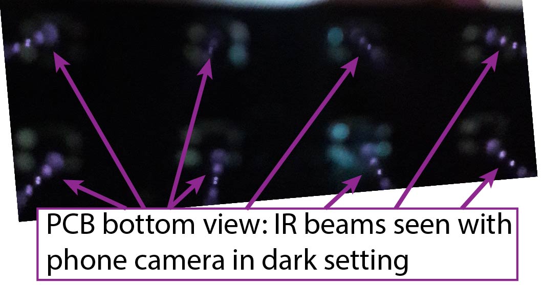
Option B: Use the camera of your phone (you should see a purple beam, although this works more or less depending on your phone/camera, you can try to go in a dark place and change the angle between the camera and the board to better see the IR beam, see picture below).
In case you see no signal from the IR LED, make sure soldering is appropriate and if fiddling with soldering doesn't work, try replacing the QRE1113 sensor (some have failed during our test perhaps due to overheating during soldering or manufacture issues)
6. Final soldering and IR checks
Disconnect USB cable and solder the 15 other QRE1113s, their associated resistors and the RJ12 connector as indicated in yellow in the above image.
Repeat the IR LED emission test (from step 5) on all other QRE1113s until all work
7. Final test
Opening the serial monitor
To test the board, connect the USB cable, open the serial monitor in Arduino IDE and make sure to choose the "Both NL & CR" option at the bottom right of the serial monitor (needed to have access to the menu).
Interacting with the board
You can use the serial monitor to send different instructions to the BCM. Below is a list of the instructions avaiable.
- h + ENTER: Help menu that will show you the different menus you can enter by typing the first letter + ENTER.
- c + ENTER: Show the hexadecimal values of the IR values read from the sensors. When passing your finger or a pencil over a sensor, you should see its corresponding value change.
- s + ENTER: Display the current values of settings A to Z.
- A: Log ID
- B: Number of seconds since the card was started (uptime)
- C: number of exiting bees through gate 1
- D: Number of entering bees through gate 1
- E: Number of exiting bee through gate 2
- F: Number of entering bees through gate 2
- etc...
You can move a pencil over a gate in both direction and retype 's'+ENTER to update the values on the serial monitor screen.